|
|
|
|
|
|
Go to | Viking Negative Plates |
Viking tech bulletins |
 Download a PDF version of this page. Download a PDF version of this page.
Technical Bulletin TRM/95Introduction This Technical Bulletin contains recommendations by the Exposure Systems Corporation about Theimer Violux lighting systems and Theimer THS bulbs. Theimer Violux lighting systems include 5KW Models 5002, 6000 and multi 6 and the 7.5 KW Models super and multi 10. This Technical Bulletin will cover areas in:
* Bulb Type and Age Bulb Type and Age Theimer recommends that for optimum performance, use only THS designated Theimer bulbs in all Violux units. Theimer multispectrum bulbs are color coded with a white band at each end of the glass envelope; diazo bulbs are identified by a gold band at each end of the glass envelope. Both Theimer multispectrum and diazo bulbs work well with Viking™ plates. All Theimer bulbs are warranted not to lose more than 20 percent of their normal UV output in less than 1000 hours of use. Bulbs should be replaced according to the following recommendations:
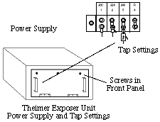
*Every 60 days in a 24 hour round-the-clock operation A record should be kept of each bulb change for troubleshooting purposes and maintenance requirements. Thoroughly clean the safety glass after each bulb change. A dirty safety glass can increase exposure time by as much as 50 percent. Avoid frequent shutdowns and restarts; each restart shortens the bulb life by several hours. Proper Line Voltage To obtain optimum performance from a Theimer bulb, the exposure unit transformer (located inside the front panel on the left side of the power supply) must be tapped to match the incoming line voltage. Exposure units are factory set at tap setting 3 (240 Volts) which often does not match the incoming line voltage. To determine the proper tap setting, a qualified electrician should measure the incoming line voltage (underload) with a volt meter. The chart below gives the incoming line voltage and its correct tap setting.
Theimer believes that at least 25 percent of exposure unit installations are operating with the wrong tap setting because they were never checked at installation. For example, an exposure unit set at tap 3 (factory-set) with an incoming line voltage of 220 Volts (tap 2) results in longer exposure, shorter bulb life and greater exposure/bulb instability.
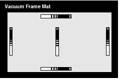
Light Source Height The recommended glass-to-glass height is approximately 80 percent of the diagonal of the area to be covered. For example, to fully expose a 42-inch plate with minimum falloff, the glass-to-glass height should be 41 inches high. To check for falloff, follow this procedure. 1. Place the plate so it is centered beneath the light source. 2. Place a gray scale on the sides, top, bottom and middle of the plate. 3. Expose at normal exposure. 4. Develop the plate. 5. Read the gray scales. The gray scale readings on the sides of the plate should match each other and not be more than 1/2 step different from the center gray scale reading.
Gray Scale Locations on Plate


Copyright 1996 Imation. All rights reserved. 
|